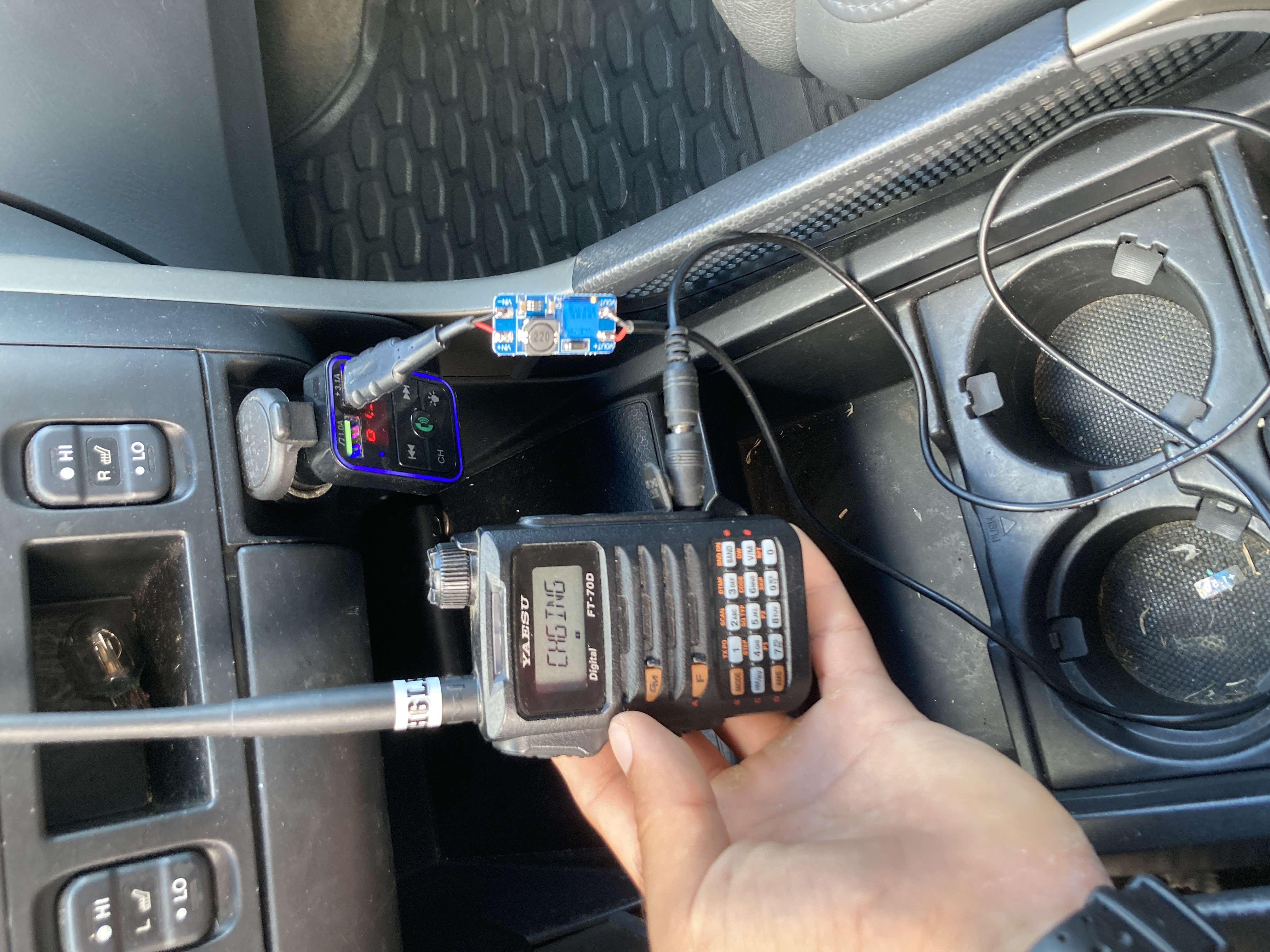
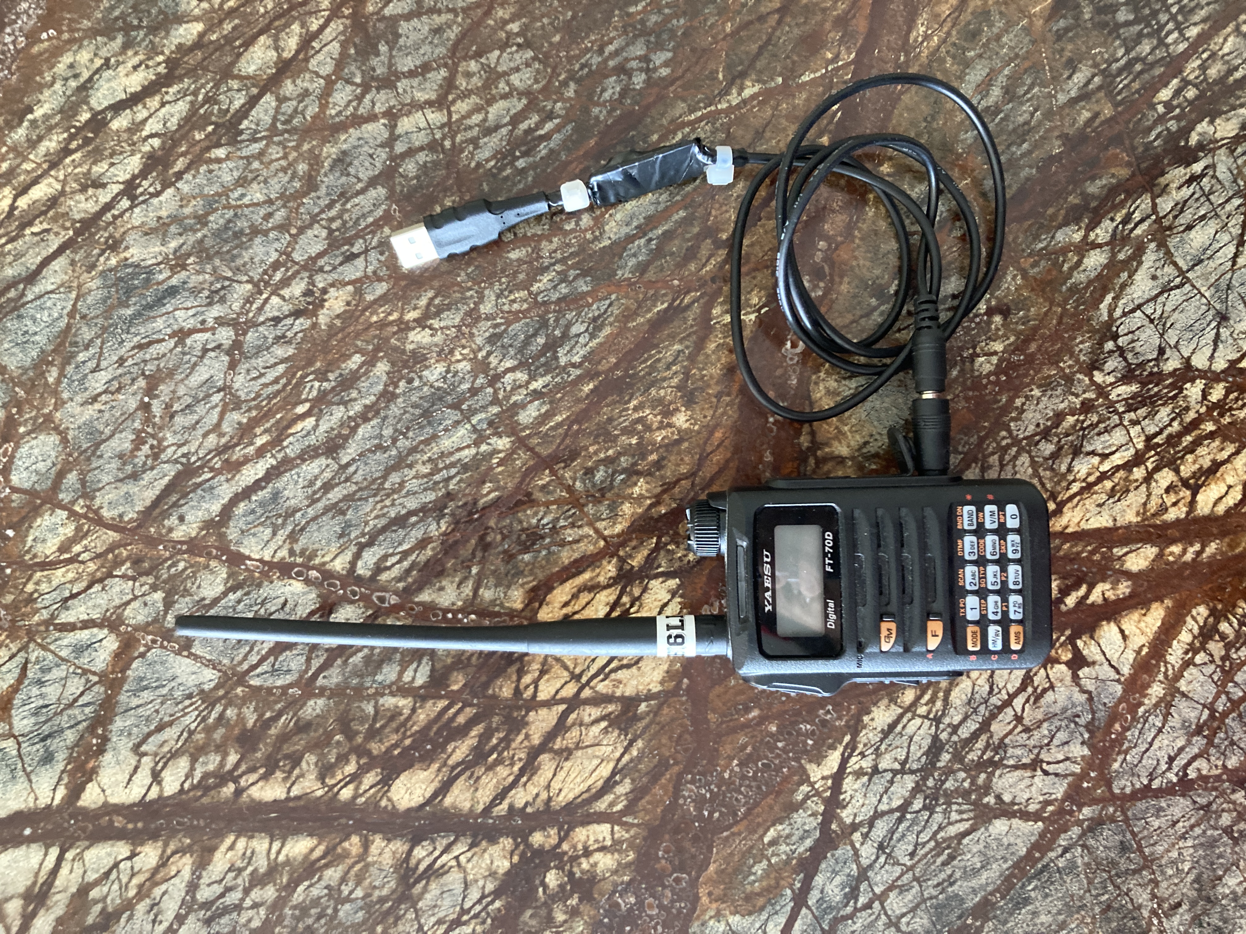
If you use a Yaesu FT-70, the ability to charge it via USB is very convenient. Many users complain of the FT-70's poor battery life, which requires frequent charging. This article will demonstrate how to build such a cable that will not only let you charge your radio anywhere you go, but will also only cost a few dollars. I use the cable in my car as a way to charge my FT-70 on the go, and it works great. It has a smaller profile than other chargers available on the market, which is quite nice. Additionally, the MT3608 boost converter module is specified to source 2A, meaning it should charge the radio in half the time as the stock charger, which only supplies 1A. Furthermore, It is a simple and fun project suitable for beginners in electronics and soldering. During the build, It is important to correctly identify the polarity of the wires and the output voltage of the converter as it may damage the radio otherwise! Please understand that this information is provided for educational use and that I am not liable for damage that it may cause. With that out of the way, lets get started!
The parts:
To build this charger, you can use whatever cables you may have on hand, as long as one of them has a plug with a 4mm outside diameter and 1.7mm inside diamater (the connector to the radio), and a USB male connector. The build is very flexible and most parts can be found in a junk box or thrift store.
I used the following parts:
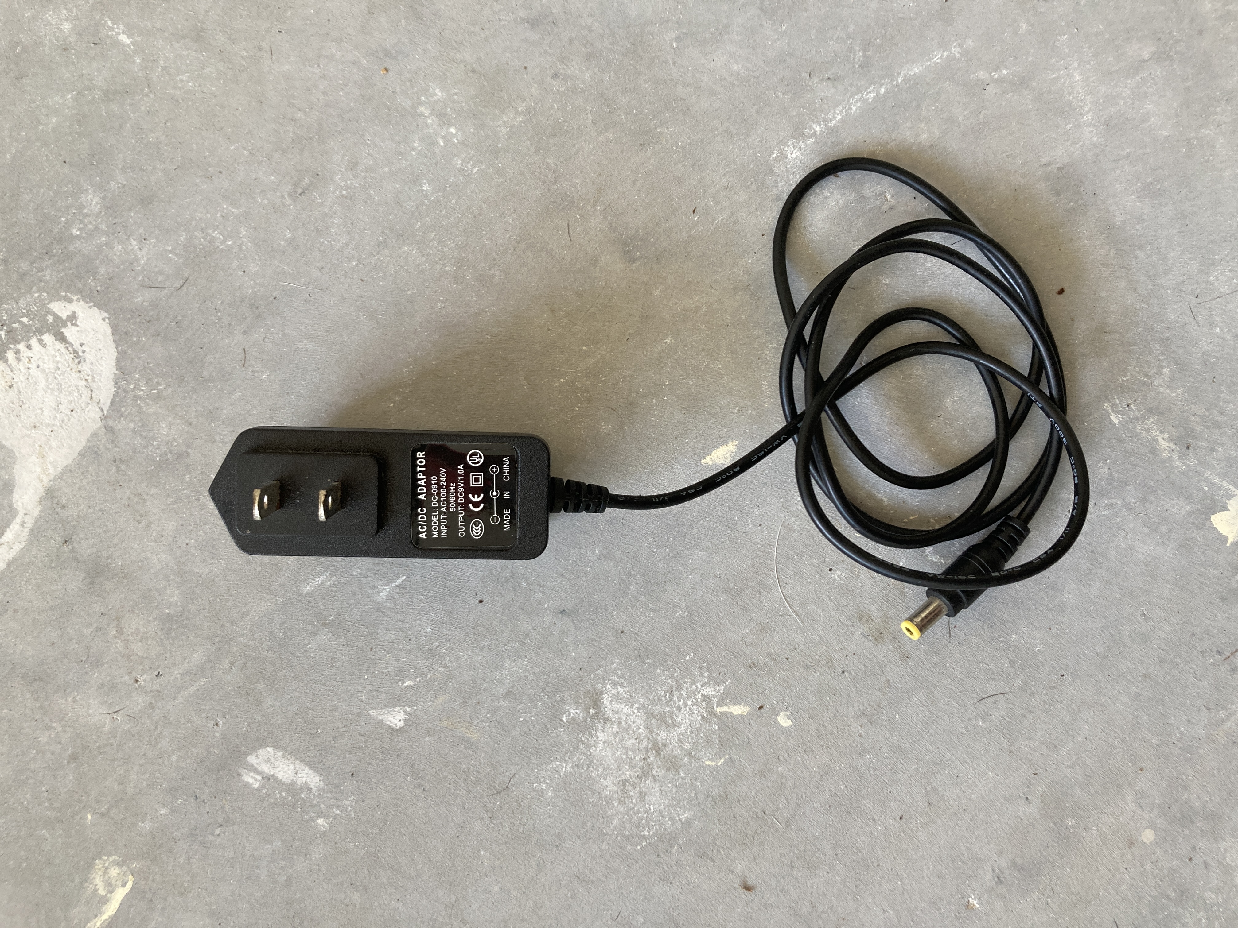
- A 9VDC wall adaptor with a barrel jack.
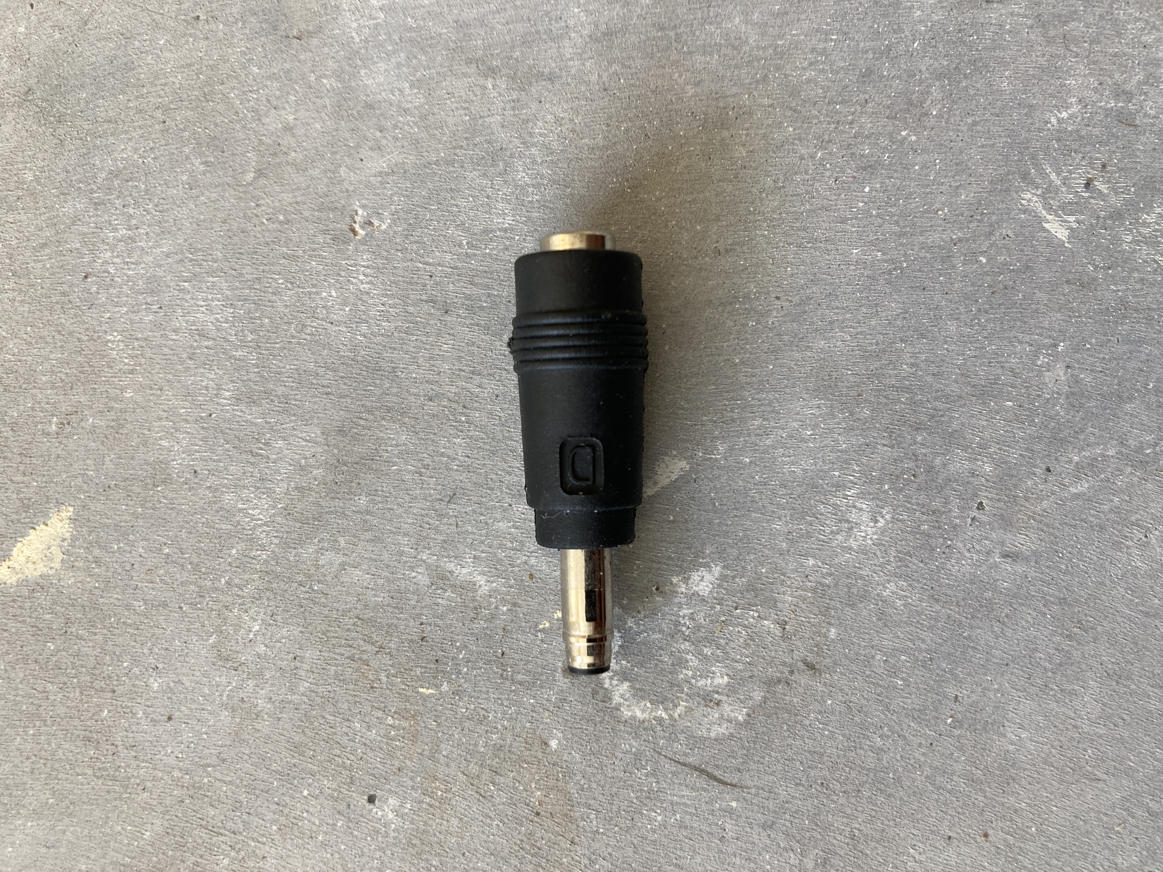
- An adaptor from the barrel jack to the FT-70 plug (4mm O.D. x 1.7mm I.D.) This plugs onto the barrel jack on one side and plugs into the radio on the other. If you have a cable which terminates in the radio plug instead, you don't need this adaptor.
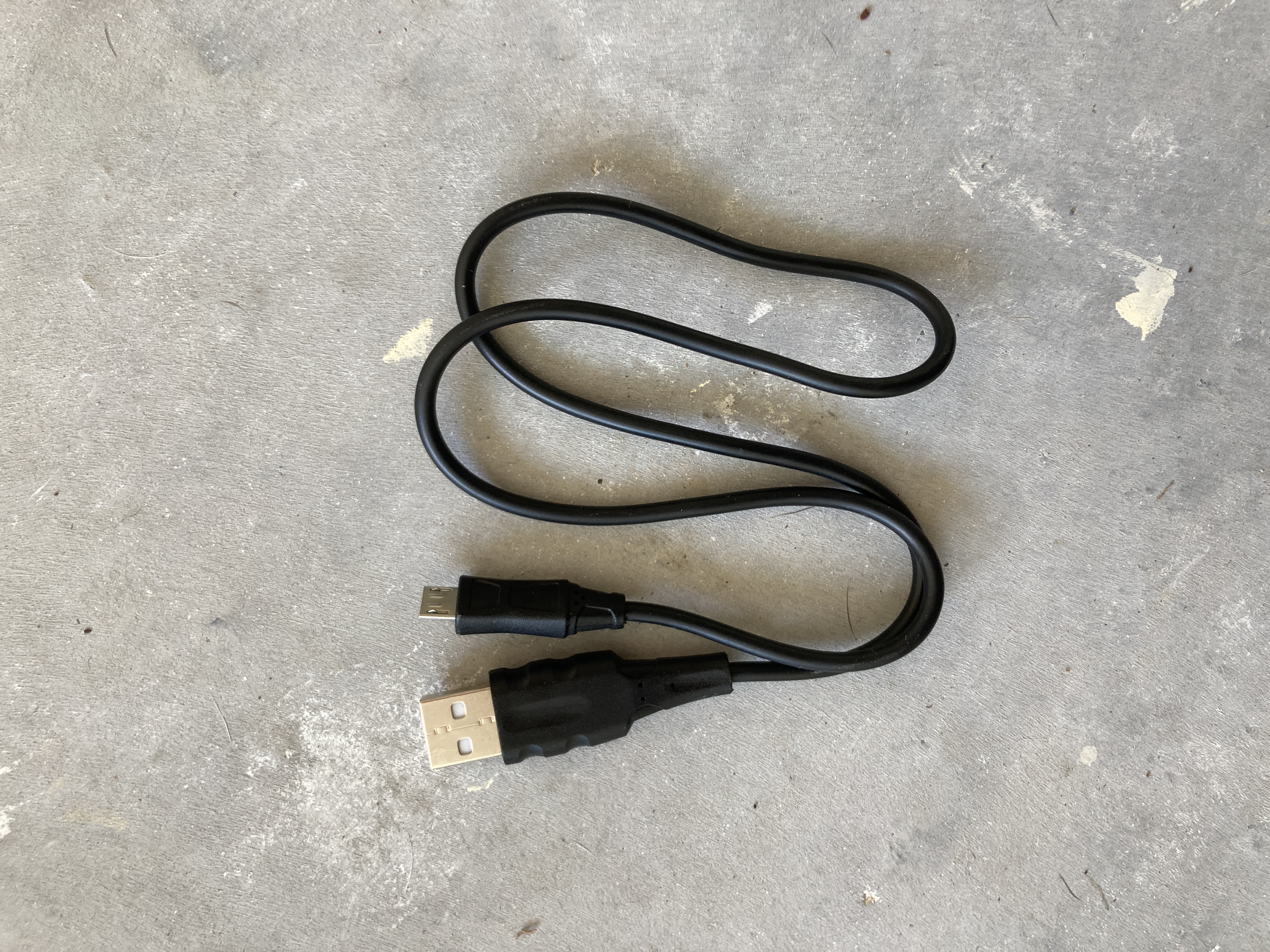
- A USB-A phone charger This is a simple USB type-A charger that was supplied with a cellphone. They can be found very easily.
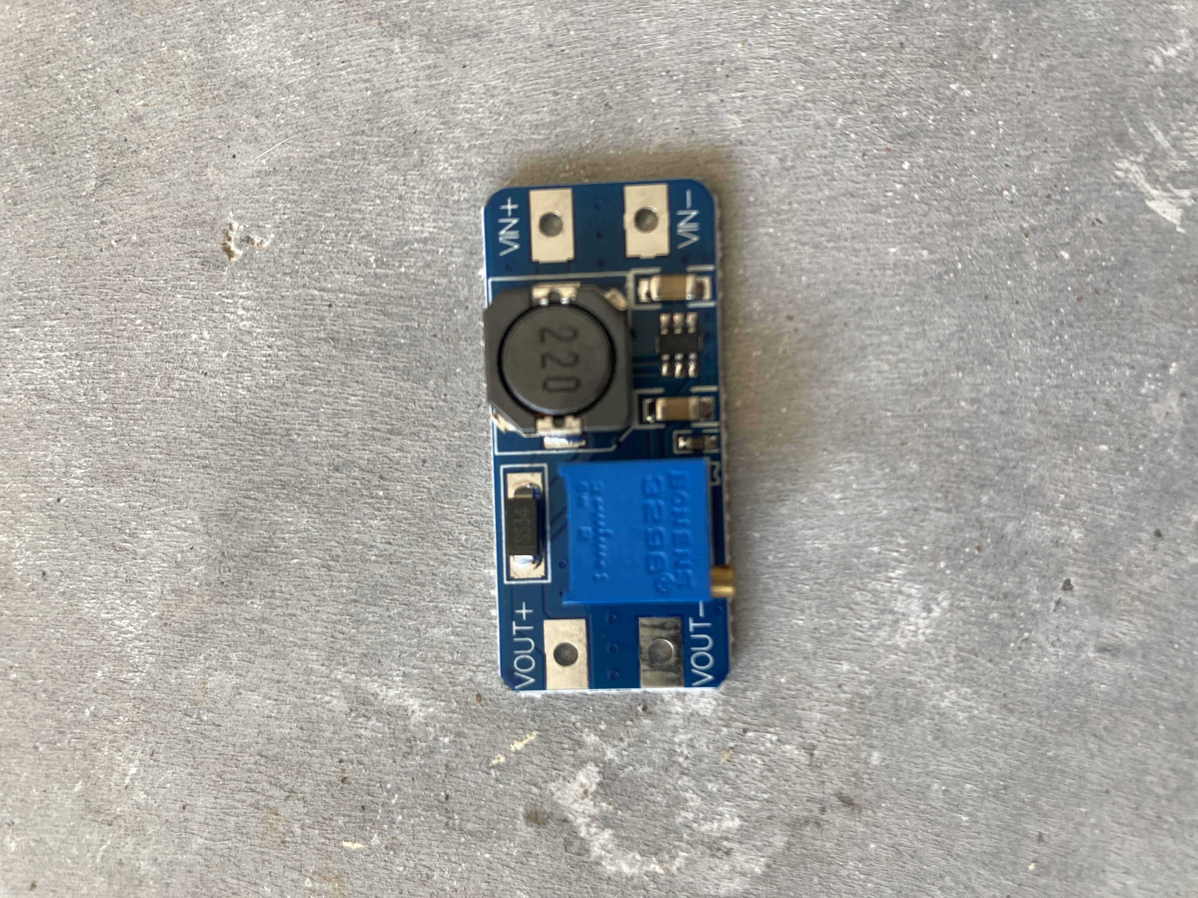
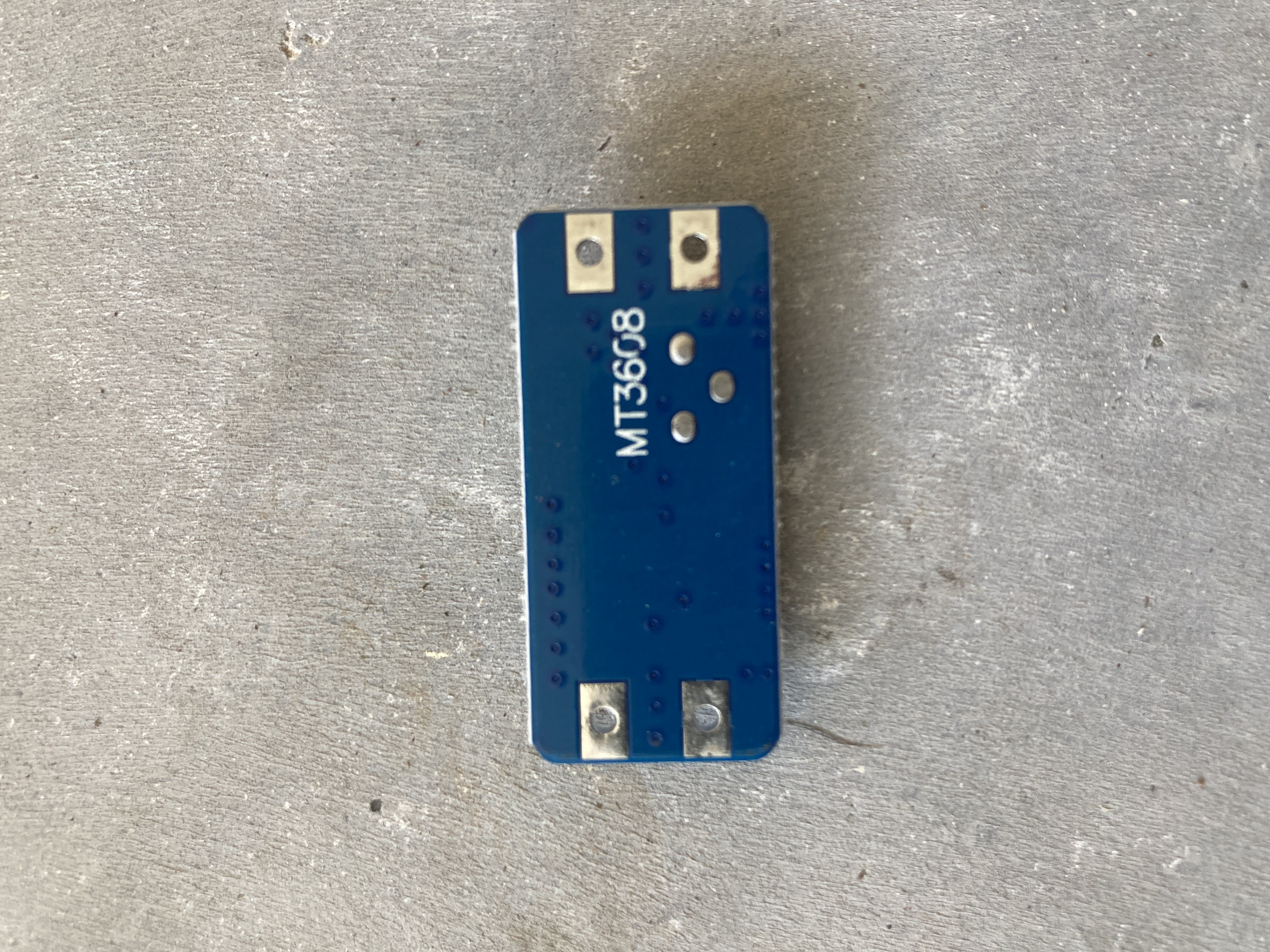
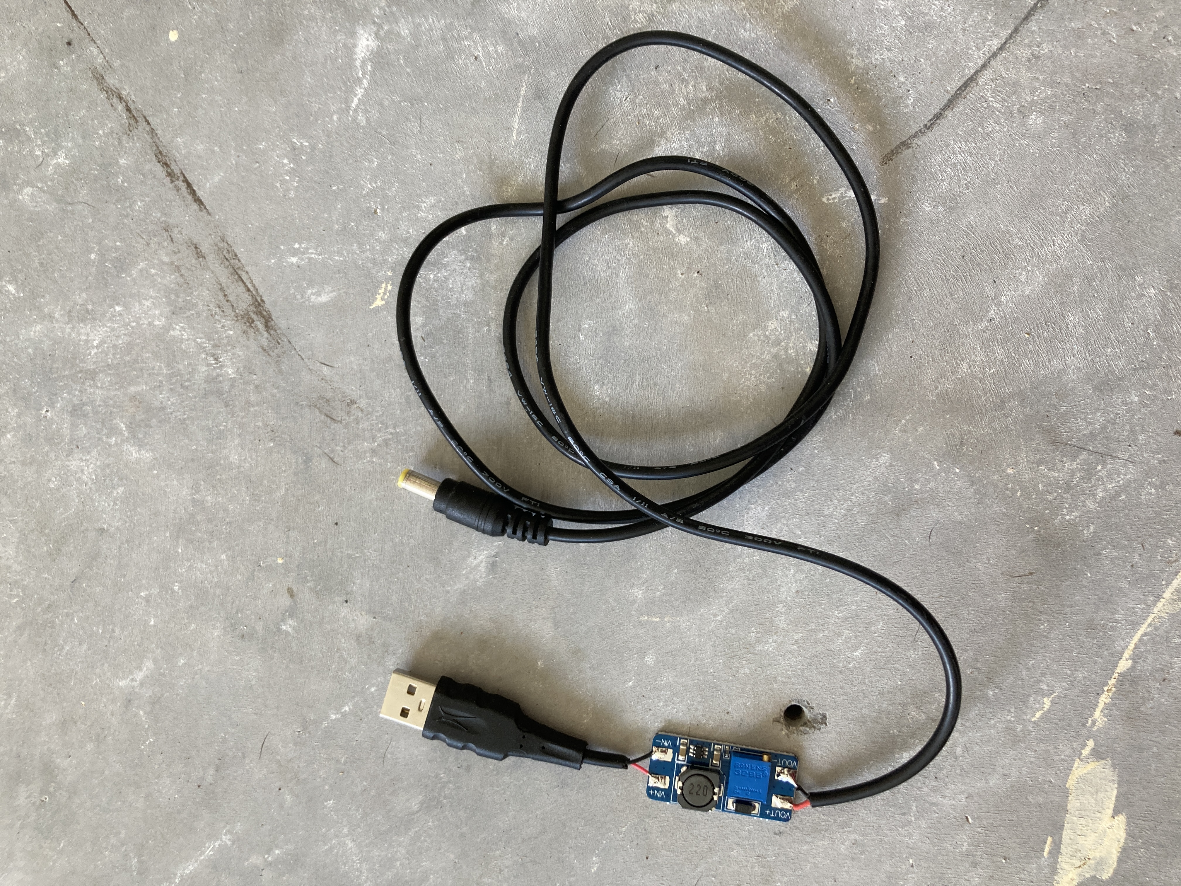
- And an MT3608 Boost Converter Module. This one might be a little harder to come by but I got about 5 of them from Aliexpress for less than a dollar. Here is the link. This part boosts the voltage to a level sufficient for charging the radio (10.5v). It has a built-in multi-turn potentiometer that is used to vary the output voltage, and can supply about 2A. This is more than enough for our application as the stock FT-70 charger only sources 1A. You can also purchase a "buck-boost converter" which also allows the voltage to be reduced. Using a buck-boost converter would allow you to construct a universal charger that would work with any input DC voltage, including: car batteries, solar panels, USB, and more. By using a boost converter like the one shown here, only input voltages less than around 10.5V can be used. We are using USB (which is 5v) so this is perfect. If instead you have a buck-converter, only input voltages above 10.5v may be used. This is good for creating things like cigarette outlet charging cables.
Building the cable:
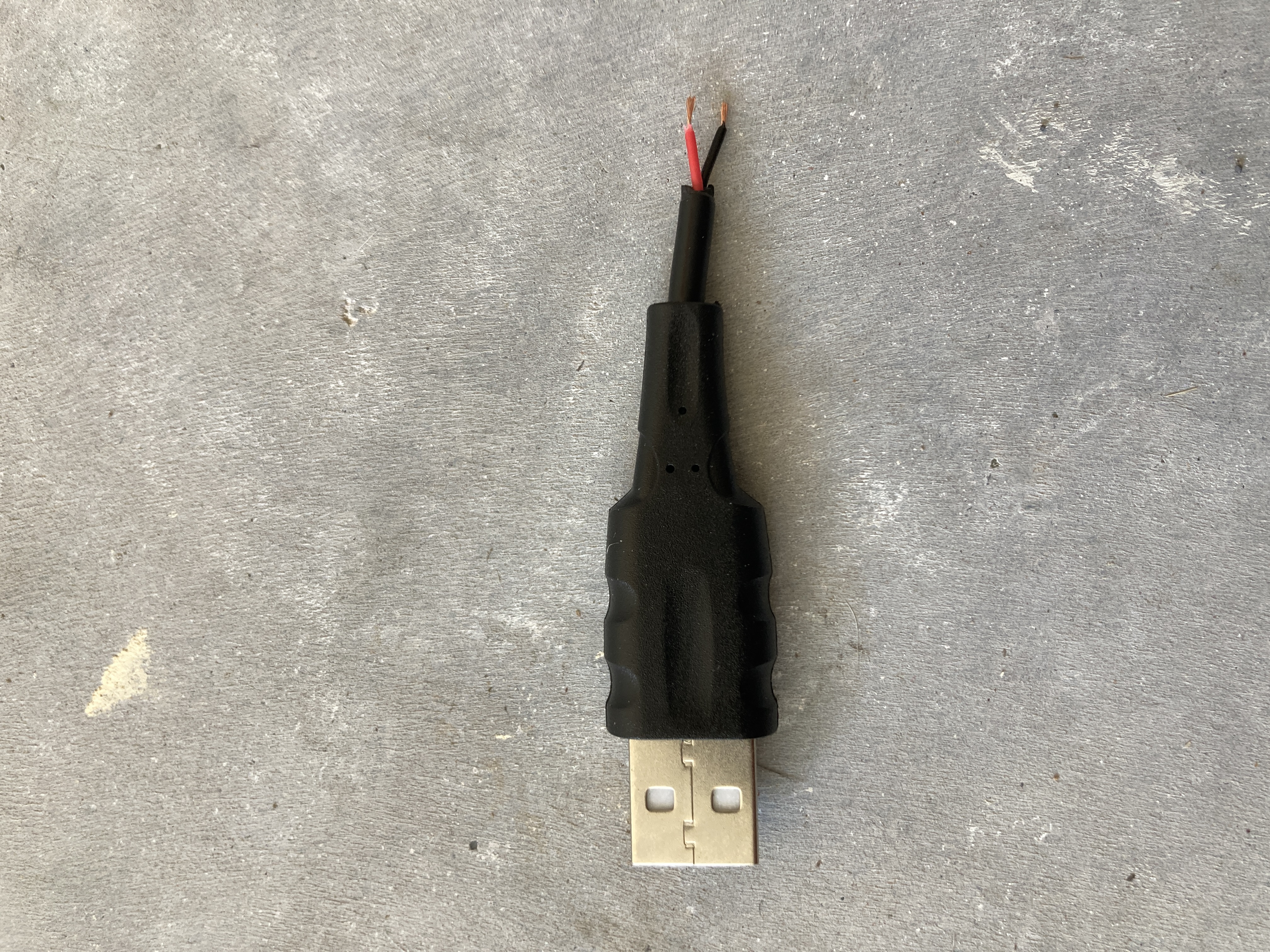
The first step to build the cable is to splice the USB connector. To do this, simply strip the insulation a few inches from the connector, revealing the wires inside. Identify the power lines by stripping each wire, plugging it in, then measuring the voltage across each wire. The pair of wires carrying the 5 volts are power.
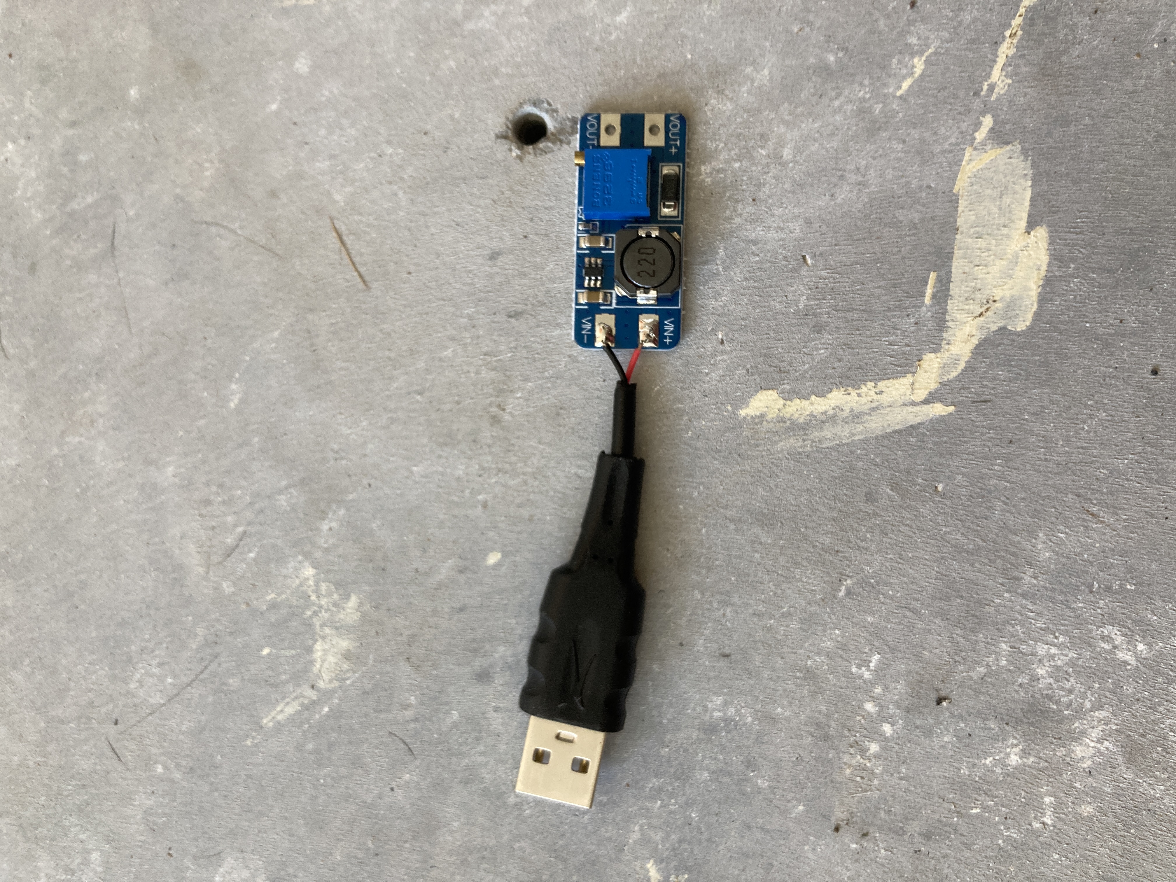
Next, tin the power wires of the USB connector and begin soldering it to the input of the MT3608. The positive and negative power-carrying wires on the connector should match the polarity of the boost converter.
The next step is to solder the output cable which will connect to the radio (in my case, via an adaptor). Cut the end off your cable, leaving a few feet of length to work with. Strip the insulate about an inch from the end, then strip the ends of the inner conductors.
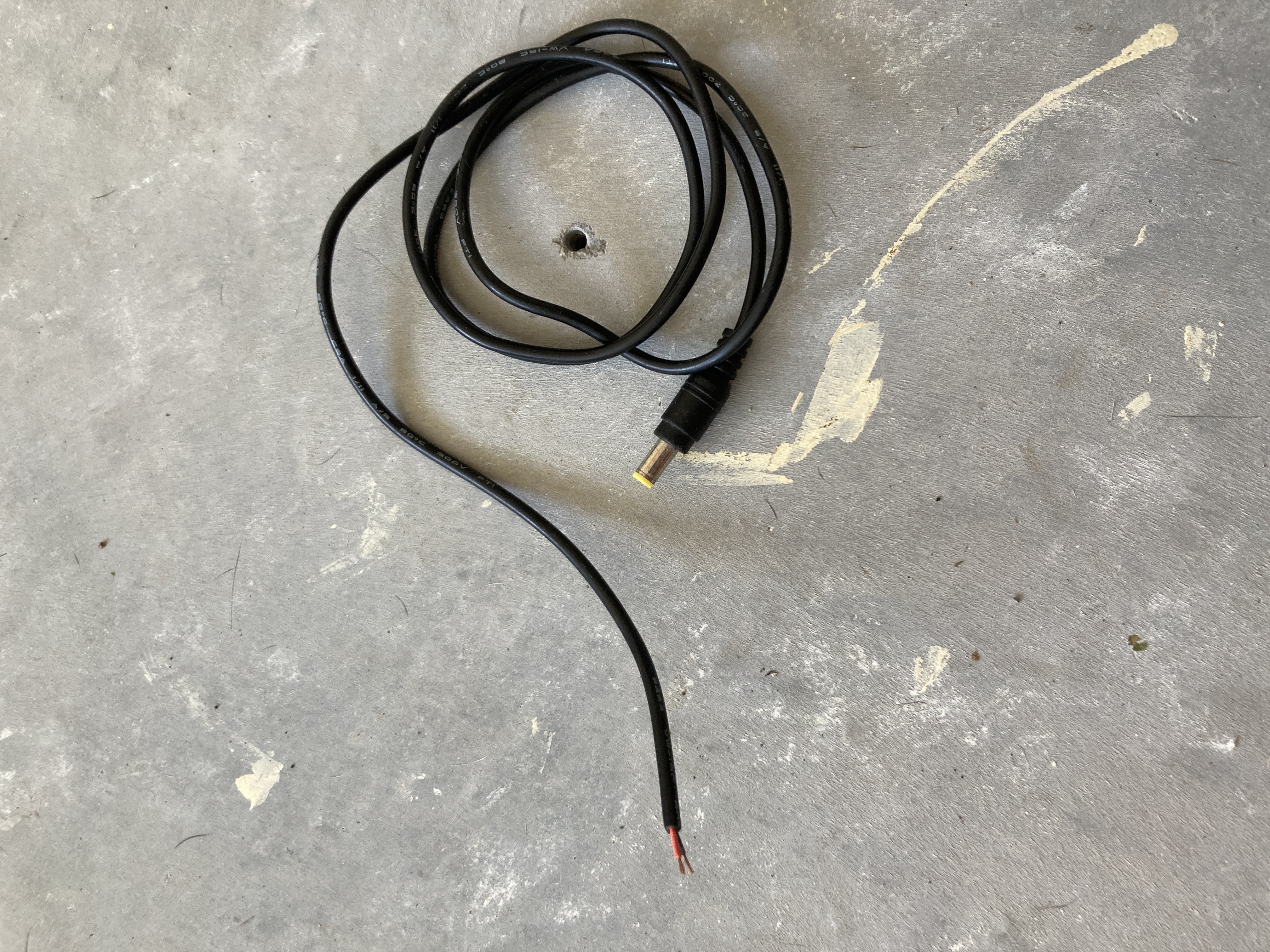
Determine the positive and negative leads of the cable and solder them to the output of the boost converter. To do this, turn your multimeter to conductivity mode and place one lead on one wire and the other lead on the outside metal part of the plug at the other end. If your meter beeps, this means this wire is ground, and you can solder it to the ground pad of the boost converter's output. If it does not, solder it to the other output pad. Solder the other wire to the other connector and that should complete this step. Some wires may already be marked red and black, but I find it best to double check.
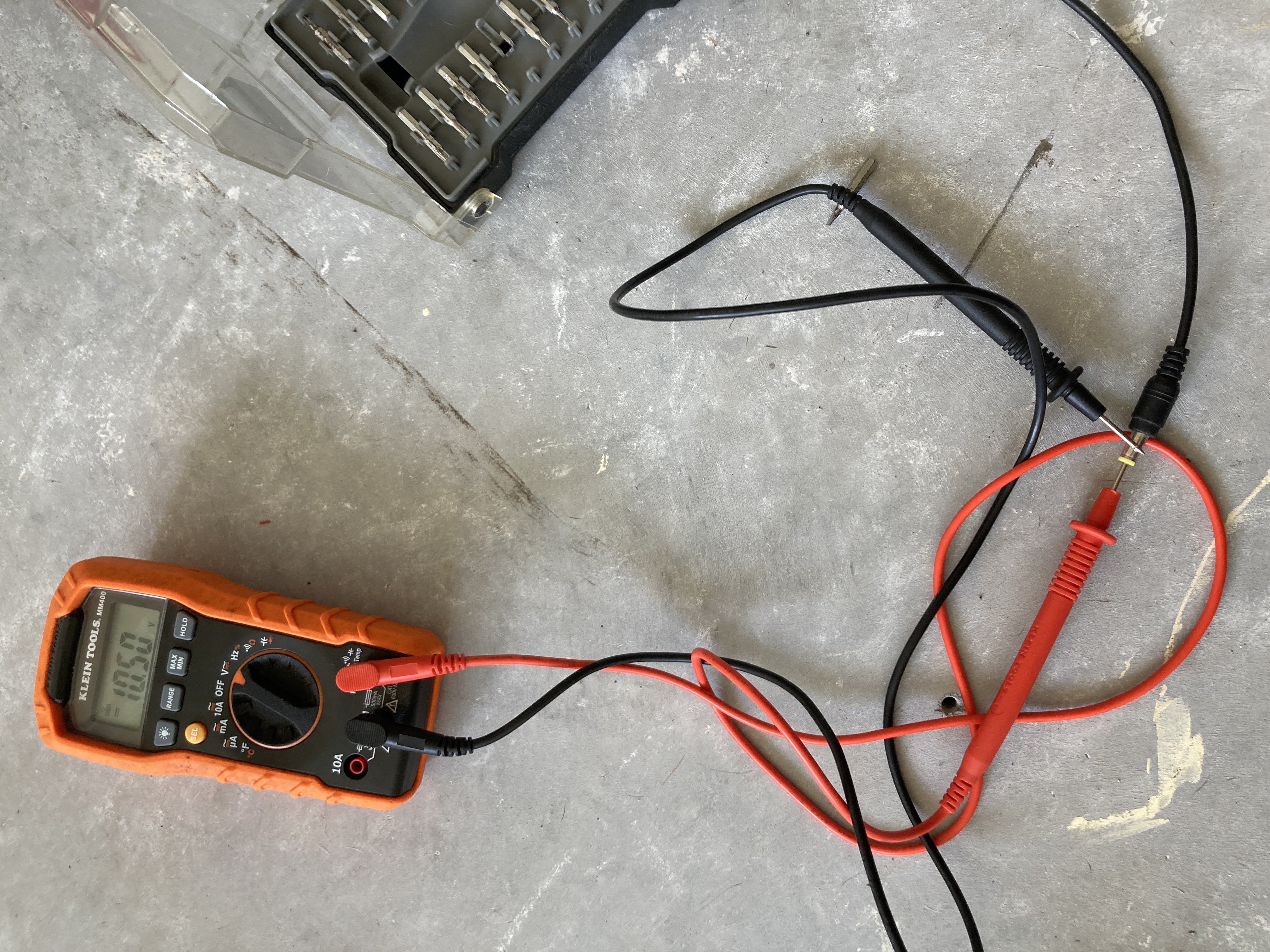
After you have completed the soldering, the final step of the build is to adjust the voltage of the boost converter. Plug the USB end of the cable into a socket and place one of your multimeter leads into the plug on the other side. Next, place your other lead on the metal barrel on the outside of the plug. The inside of the plug is power and the outside is ground, and here we are simply measuring the output voltage. Turn the potentiometer on the boost converter and observe the voltage at the output. Do not worry if you as you turn it and the voltage stays the same. Just continue turning it until you see the voltage begin to climb. If after a while it doesn't, then try the other direction. Keep turning the potentiometer until the voltage reaches 10.5v. This is the charging voltage of the FT-70, which shouldn't be exceeded.
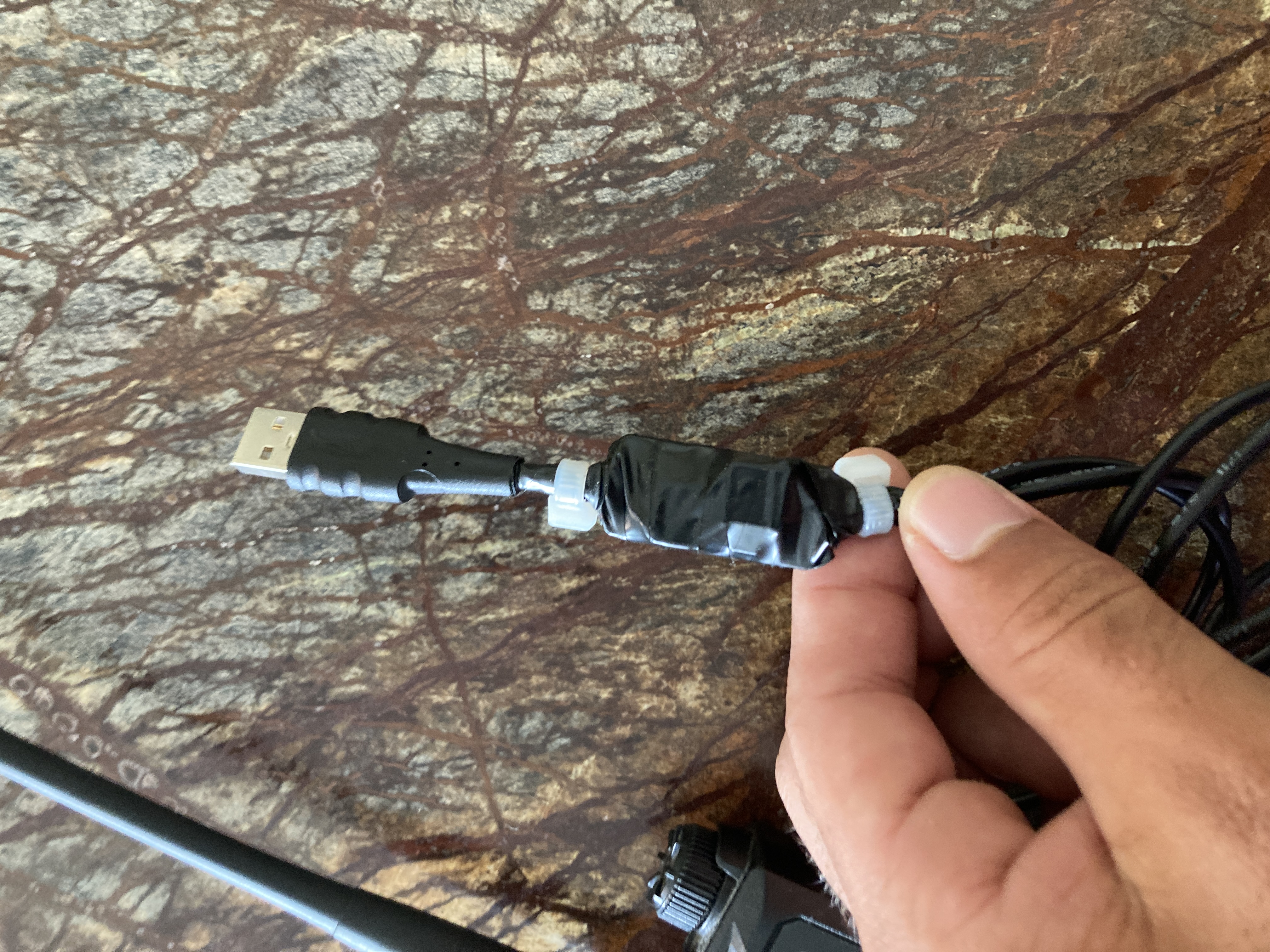
Once you are finished adjusting the voltage, your charging cable is complete! You may choose to put a layer of heat shrink over the converter module or wrap it in electrical tape, which is what I did. Alternatively, if you have a 3D printer, you could even make a small enclosure for a more professional look.
Thank you for reading this article and I hope you had success in creating your own simple USB charger for the Yaesu FT-70.