The ability to generate signals across a wide frequency range is extremely useful. It allows you to characterize filters, perform receiver tests, and more. I've been wanting to add one to my lab for a while now, but was discouraged by their price. As for most test equipment capable of operating in the microwave region, they don't come cheap. Fortunately, I have a HackRF transceiver, which I used to create a 6GHz signal generator. Since the modulation of the output signal is limited only by the DSP software running on the computer, very complex waveforms can be created with no additional hardware. It will obviously not grant as much flexibility as a dedicated machine, but these key features allow a powerful signal generator to be realized for very little money. Keep reading, and I'll show you how to build it yourself.
How does it work?
A signal generator is simply a piece of test equipment that generates an RF signal. If it is capable of producing standard waveforms like sine, square, or sawtooth, it is called a function generator. For my purposes, I need a signal generator capable of producing signals into the high UHF range, maybe about 3-5GHz. If it could cover the 5.8GHz band as well that would be great. I would also like the ability to modulate an audio carrier onto the signal, which would allow me to perform certain receiver characterization tests. My primary goal is to generate sine waves, but other waveforms would be nice too. However, the bandwidth of the SDR limits the types of signals it can generate. As such, it is unable to create square waves and other wideband waveforms. Now that we have defined the requirements for the signal generator, we can begin to explore its workings.
As previously stated, this signal generator uses the HackRF One at its heart. If you are unfamiliar with this device, it is a half-duplex software defined radio transceiver capable of operating between 1MHz and 6GHz. It has an 8-bit ADC and DAC capable of 20MSPS quadrature sampling. This allows an instantaneous receving bandwidth of up to 20MHz. There are also built in RF variable gain amplifiers on both the input and output signal chains. Great Scott Gadgets, the designers of this SDR, sell the product for about $340 through various retailers throughout the world. However, chinese sellers have made copies of the open source product, which they sell for less than $100. The official Adafruit product page can be found here. Since it is an SDR, the capabilities of this device are mostly limited by the software that you run on your computer. Therefore, we can fulfil most of the design goals just by writing software for each function. This signal generator builds off a previous project of mine; a portable battery-operated SDR platform. It has a built in Raspberry Pi 4, an LCD display, a rotary encoder and other IO, a powerful speaker and amp, and many expansion opportunities. I built it to facilitate communications, perform experiments in the field, monitor trunked radio networks, and virtually every other radio-related task. It runs custom interface software which puts the power of an SDR transceiver into a user-friendly, portable, and rugged package. Although I am very passionate about this project, I will save my ramblings for a future series of articles. The point of this tangent is to explain that the signal generator will be integrated into this device. The I/O of the radio box also provides a nice physical user interface. If you want to build a similar device, I will be posting a series of articles on the details of the design. It will cover the code, CAD files, electrical schematic, general design considerations, capabilities, and more. If you are interested, please stick around for that. If you don't need a standalone interface, you can just connect the HackRF to the computer and run the appropriate signal generator software on there. This is how I will construct it in this article. In a future post, I will describe how to interface GNU Radio with a physical interface to build a fully standalone device.
Why cant it generate square waves?
Uing an SDR transceiver as a signal generator has multiple downsides. One of the most severe limitations is that it cannot produce wideband waveforms, like square waves. Any signal containing sharp transitions widens the bandwidth of a signal. For this reason, most CW transmitters attempt to modify the envelope to gradually increase the output power and thus reduce the bandwidth of its signal. This same technique is used in digital modes like Gaussian Frequency Shift Keying. A square wave is the perfect example of this phenomenon, as the rising or falling edge of the signal increases its bandwidth dramatically. A perfect square wave has components at the fundemental frequency and at every odd harmonic. This means a 1MHz square wave will include sine waves at 1MHz, 3MHz, 5MHz, and so on. The larger the number of harmonics, the more accurate a square wave that can be represented. To better illustrate this phenomena, it is helpful to visualize it in the frequency domain. Please consult the following diagram:
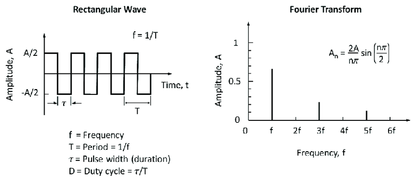
Source: ResearchGate.
An SDR transceiver cannot generate square waves because it doesnt have enough bandwidth. Consider a signal at 10MHz. You would need to create sine waves at 10MHz, 30MHz, 50MHz, 70MHz, and even higher. Obviously this is out of the question for an SDR. Even a 20MHz bandwidth SDR like the HackRF would only cover the fundemental. For this reason, it is extremely difficult to generate these types of signals with any type of SDR. This also applies to the triangle and sawtooth waves (which also contain the fundamental and every odd harmonic). However, I am not terribly concerned with this limitation as square waves are much easier to generate over a wide bandwidth than sine waves. A single $3 chip like the SI5351 could be used to do this.
How to build it
The minimal hardware setup for this project is very straightforward: Get a HackRF and plug it into your computer. In my case, I used a Raspberry Pi 4 which I VNCed into. I found the performance adequate to run GNU Radio.
Software
The bulk of this project is the software. The first step is to install the required dependencies and software packages. You may already have most of them installed. If so, feel free to skip it. The two most important software packages are HackRF Tools, gr-osmosdr and GNU Radio Companion. GNU Radio Companion is a graphical tools that generates code utilizing the GNU Radio framework. If you use an ubuntu-derived linux distro, a simple "sudo apt-get install gnuradio" will probably suffice. Otherwise, consult the official documentation linked above. The HackRF tools were a bit more challenging as I could not find them with apt. In this case, I just built it from source. If you need help with this or with installing dependencies, this article has a lot of information. To install gr-osmosdr, consult the Github documentation. The steps to build from source are found in the README:
git clone https://gitea.osmocom.org/sdr/gr-osmosdr
cd gr-osmosdr/
mkdir build
cd build/
cmake ../
make
sudo make install
sudo ldconfig
After you finish installing the software, open GNU Radio Companion and run an example flowgraph to ensure your installation is working properly. The source or sink block should be set to "Osmocom" to work properly with the HackRF. Then download the .grc flowgraph file from here and open it with Gnu Radio Companion. It should look like this:

Alternatively, you could recreate the flowgraph from this screenshot, but thats a lot of work. The flowgraph was based on a post by Marcus Muller on the Amateur Radio Stack Exchange. All I did was modify it to work with the Osmocom Sink. It is a simple program feeding a signal source into the Osmocom sink. There are some other GUI elements like sliders and an FFT window, but they just control the frequencies and gains and display the generated signal.
Using it
To use the signal generator, click the grey "play" button within Gnu Radio Companion. If there are no errors, a new window should open. If it doesnt, try closing other programs on your computer that are using the HackRF, like GQRX or hackrf_transfer. If that still doesn't work, try double-checking your installation. Use the carrier and tone frequencies to adjust the carrier and tone, respectively. The tone amplitude slider can be used to change the strength of the modulated audio tone. Some images of my test setup are attached below. Note that the displayed frequency on the oscilloscope may differ because of the modulated audio tone on the carrier.
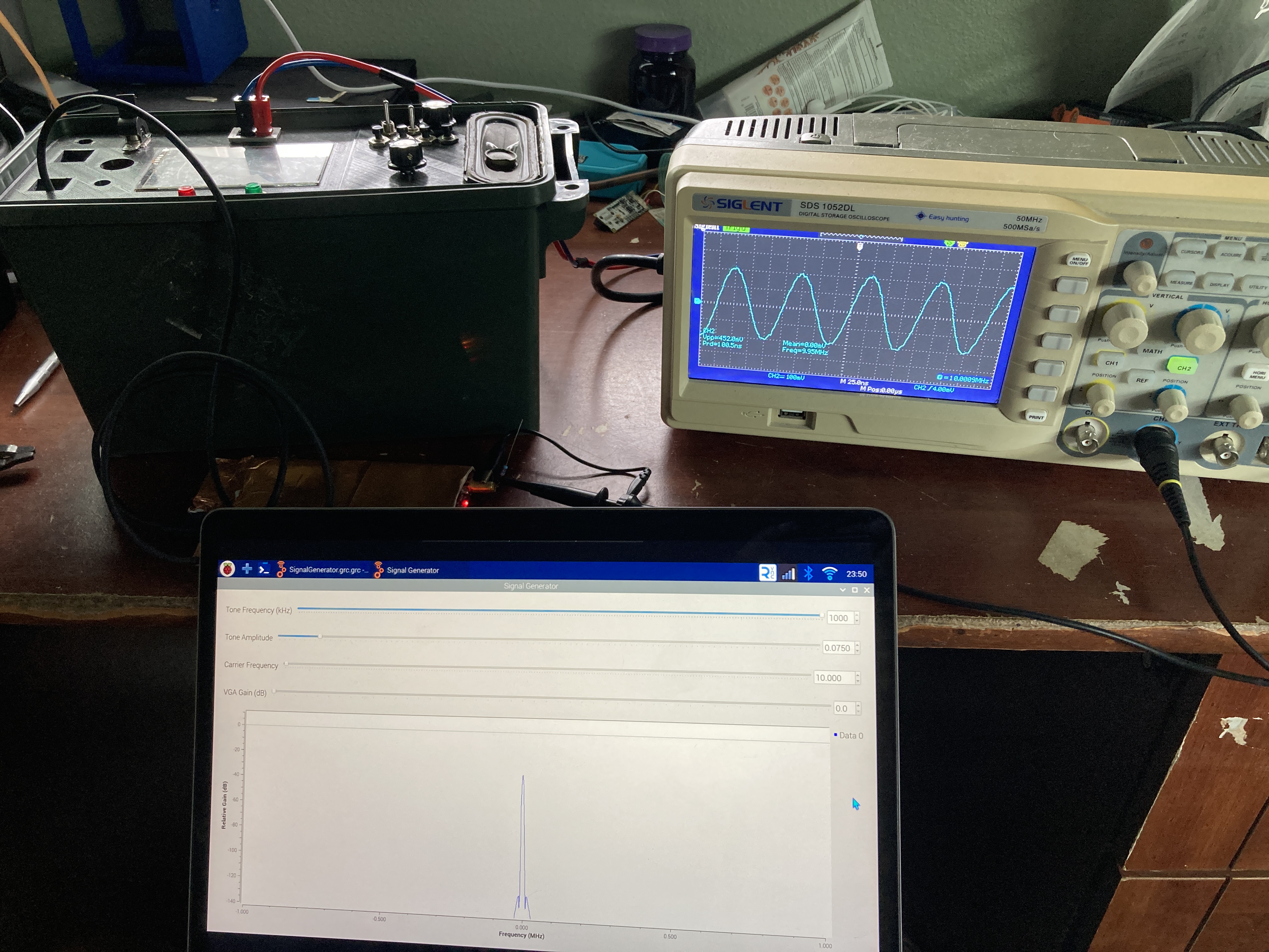 10MHz sine wave generated with the HackRF One.
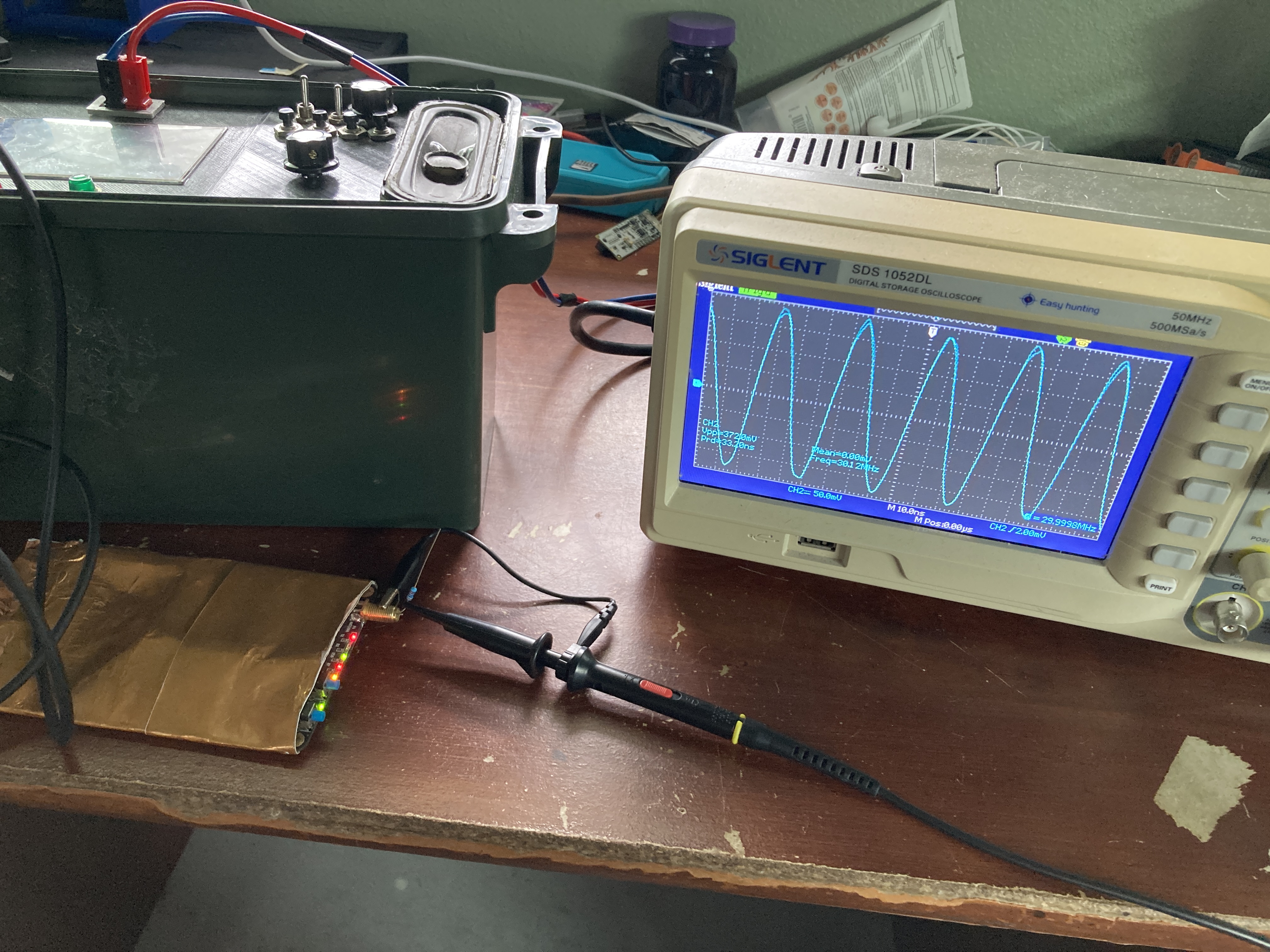
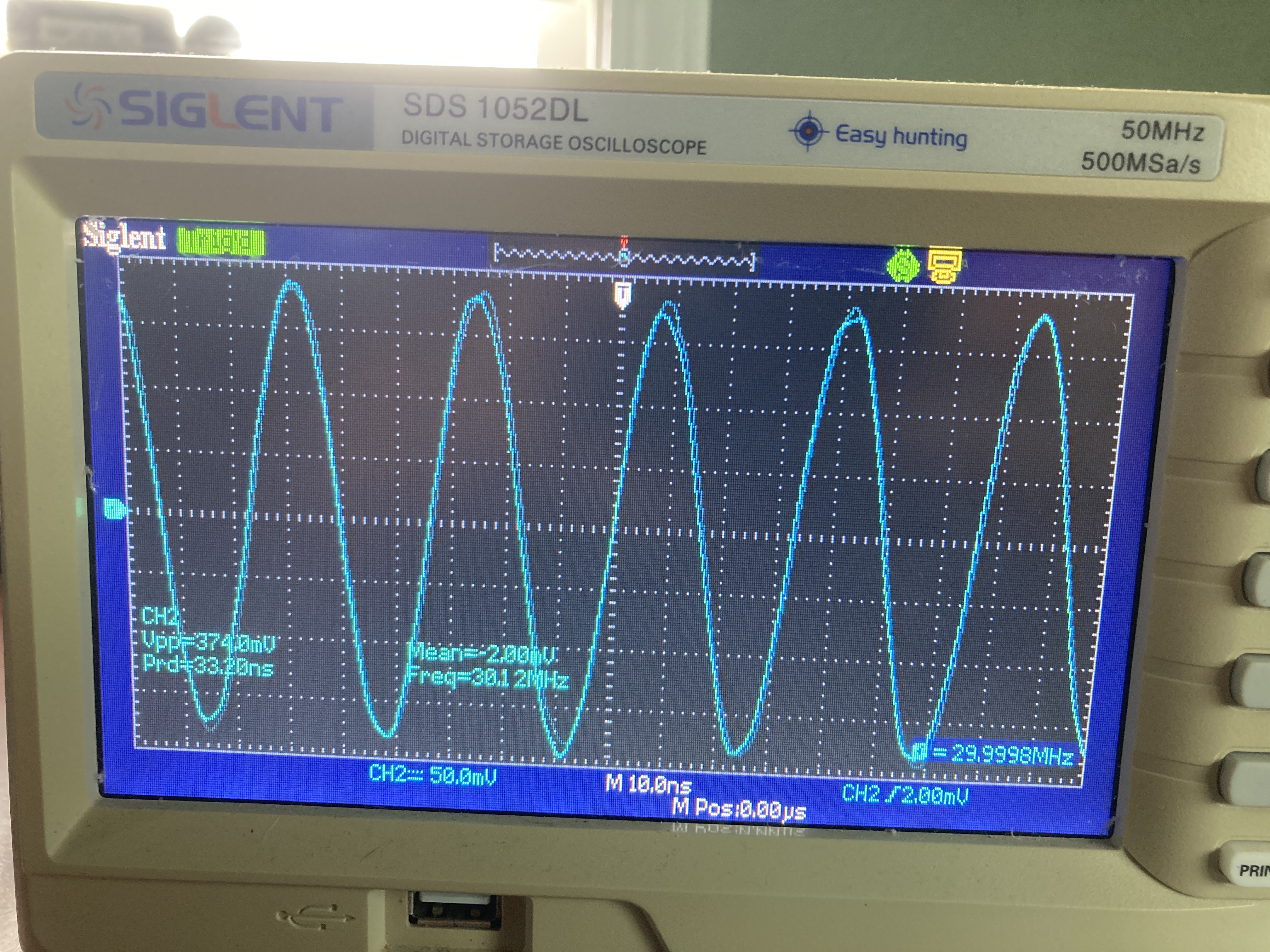 30MHz sine wave generated with the HackRF One.