In a previous article, I covered a design for a time difference unit intended to be used for a phased array antenna. It used microstrip lines and demultiplexers to route RF signals along paths of various lengths. The main drawback of this design is its complexity, criticality of transmission line lengths, and that it can only be used on one band. Furthermore, it is classified as a passive electronically scanned array (PESA), which is inferior to the AESA in many ways (I will explain the difference here shortly). That design was optimized primarily for cost, as I wanted to build a phased array for cheap. This same goal has been kept with the new design. Since releasing that article, I continued pondering about phased arrays until I landed on the design presented here. I wanted this to be a general purpose phased array suitable for RF experimentation, satellite work, direction finding, terrestrial radio communications, radio astronomy, and more. The specific goals of this design are listed below:
- Wide frequency range
- Transmit capabilities
- Utilizes a single transceiver
- Low cost
With that in mind, lets begin exploring the design of this phased array, starting with an explanation of some essential terminology.
AESA vs PESA
![]()
A phased array antenna consists of an array of individual antennas. Each of these antennas, or elements, receive a finely controlled time delay (known as a phase shift). By altering the phase of each element in a controlled manner, directionality can be achieved (see the above diagram). If a beam to the right is desired, the leftmost element will transmit first, followed closely by the one next to it, then the next, and so on. The same is true for receiving applications. All phased array designs (whether AESA, PESA, or some hybrid) operate on this principle. Now that we understand the basics of phased arrays, lets explore three popular approaches to achieve the phase shifts.
-
The simplest example of this type of antenna is the fixed phased array. It implements fixed lengths of transmission line after every element in the array, combining to a common point at the port of the radio. Due to the velocity of propagation (the time it takes for a signal to travel through a medium), longer lengths of wire will introduce a larger phase shift. Precise directionality of the phased array can be obtained by calculating the lengths of transmission line for a specific frequency at each element. Since the phase shift cannot be changed automatically, this type of array is suitable for only a single frequency.
-
The next type of phased array antenna technology is the PESA, or Passive Electronically Scanned Array. In this system, a computer-controlled phase shifter is implemented, allowing for greater frequency range and dynamic steering of the beam. This method is the same as those used in previous generation military aircraft radars, and was the point of discussion in my last article: Phase Shifting an RF Signal with Demultiplexers and Microstrip Lines
-
An AESA, or Active Electronically Scanned Array, is a new design paradigm for phased array antennas that implements a "TRM", which is essentially an RF transceiver, for every element of an array. Each TRM introduces a controlled phase shift of the received or transmitted RF signal in software, which allows one or more individual beams to be formed. This is the gold standard type of phased antenna for current generation fighter jets and is what we will focus on in this article. It has numerous benefits to PESA-type systems. According to Wikipedia:
The AESA is a more advanced, sophisticated, second-generation of the original PESA phased array technology. PESAs can only emit a single beam of radio waves at a single frequency at a time. The PESA must utilize a Butler matrix if multiple beams are required. The AESA can radiate multiple beams of radio waves at multiple frequencies simultaneously. AESA radars can spread their signal emissions across a wider range of frequencies, which makes them more difficult to detect over background noise, allowing ships and aircraft to radiate powerful radar signals while still remaining stealthy, as well as being more resistant to jamming.
I'm not interested in using my phased array for radar at this point, but there are other benefits to using an AESA. Chief among these is the ability to detect the phase of incoming signals and give an instant bearing of their location (if using a PESA, you would have to use a scanning beam). Furthermore, the use of a TRM at every element provides enhanced flexibility in other capabilities of the array.
The Design
 As you might image, the cost of using an RF transceiver for every element in the phased array is very high. In this article, I introduce a method of greatly decreasing the cost of such a system to a point that the average person can afford. It uses a multiplexer-switched array of antennas feeding into a single transceiver. The use of a single transceiver may seem counter-intuitive, as an AESA typically has a TRM for every element. However, by switching between antennas at a sufficiently high speed, each element can take turns using the radio, effectively achieving the same thing. Using one transceiver obviously decreases the cost of a system, but it also has other benefits. The RF front end can be switched out depending on the use of the phased array. If you are conducting radio astronomy experiments with it, perhaps a low noise amplifier paired with a 21cm SAW filter will be used. This design allows for flexibility in the front end, which is unachievable with a traditional AESA.
Multiplexer Switching
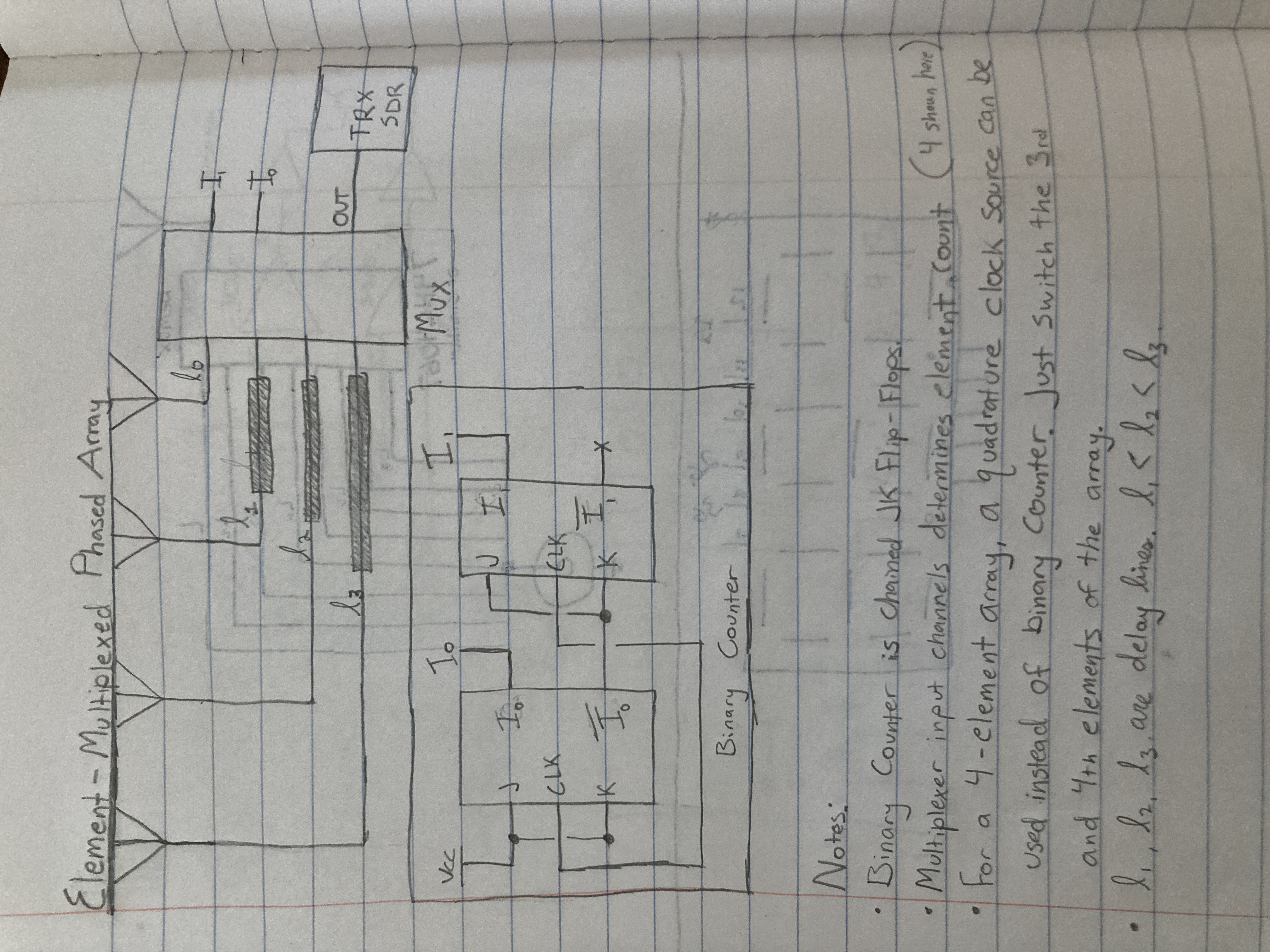
The use of multiplexers to switch antennas to a transceiver allows great flexibility, as already mentioned. However, how does it achieve this? A multiplexer is a device that has several inputs and one output. Control pins on the device allow the system to choose which input gets forwarded to the output. A high-speed binary counter constructed from chained J-K flip-flops will increment with every pulse of a clock. The binary signal of the counter will then select which input of the multiplexer gets passed through. In effect, the multiplexer will sequentially switch through each antenna one-by-one. The array can theoretically switch between an arbitrary number of elements, although more of them will degrade performance. The clock speed and switching time of the multiplexers and binary counters must be extremely fast to allow the signals from each antenna to reach the transceiver at roughly the same time. However, as computers use the same elements and can operate in the gigahertz range, I believe obtaining high speed compononts will be very easy and affordable.
Quadrature Clock Source Alternative
An alternative to using a binary counter for a 4-element array is to use a quadrature clock source. These are two square waves with the same frequency and duty cycle, offset by 90 degrees. A quadrature clock can be obtained by feeding a square wave with twice the required frequency into two D-type flip flops in a special configuration. When the multiplexer is fed with two quadrature square waves, it almost simulates binary counting. However, the third and fourth elements in the array must be switched. This is because the binary sequence for a quadrature LO signal is 00, 10, 11, 01. For it to count in a logical incrementing order, the third and fourth elements must be switched. For a visual representation of how this works, consult the truth table for a four channel multiplexer and the diagram of a quadrature square wave shown below.
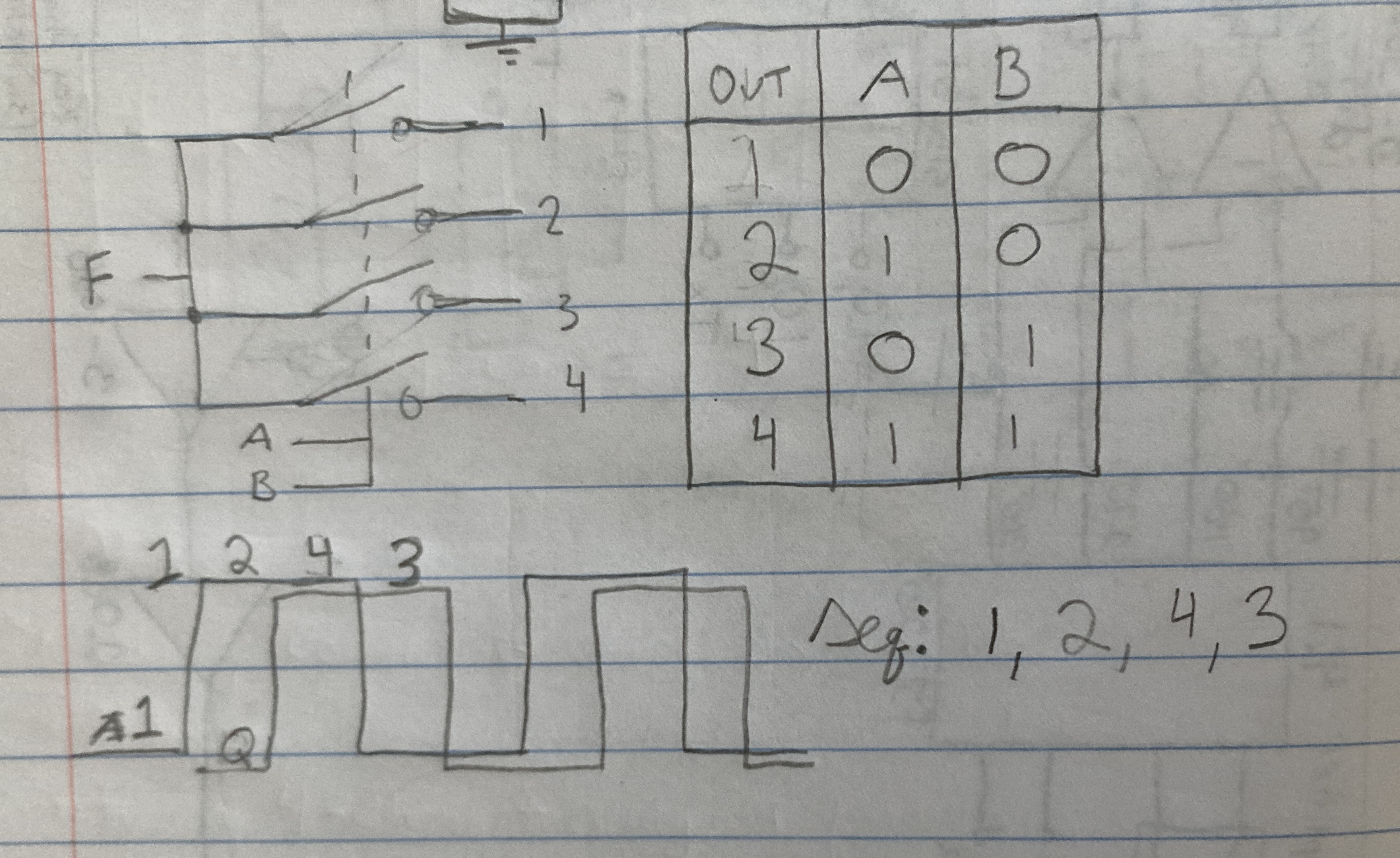
This is a special case which is only applicable for a 4-element phased array. For more complex systems, more bits are required to switch between multiplexer channels. Thus, a binary counter must be used.
Delay Lines
As it currently stands, this design will not work. When one element is routed to the transceiver, the other elements' signals are lost, so that when the next antenna is switched to, its too late. This is a problem no matter the speed of the clocks nor the propagation delay of the logic devices. This leads to the second part of my design: the delay lines. After every element in the array, a fixed transmission line with a precisely calculated length is introduced. This "time difference unit" serves to delay the signals of the other elements while the system is sampling the signals from one antenna and switching to the next array. If the delay lines are calculated correctly, the transceiver will receive signals of the same phase. The beauty of this approach is its frequency independance. Since the delay lines are dependant on the switching speed of the multiplexer and not the frequency of operation, the lengths can stay constant for any frequency of operation. Furthermore, instead of the accuracy of the phase shift depending on the amount of multiplexer channels as in my previous design, the phase shift is entirely performed in software, permitting greater flexibility. The number of multiplexer/demultiplexer channels is limited only to the amount of elements in the array. Multiplexers can also be chained to increase the number of channels at the cost of increased propagation delay and switching speed.
The example given above applies to receiving. In transmitting, the opposite is true. The system will start at the element with the longest delay line, then move its way down, implementing the phase shift in software for each element. Of course, this would have to be done with a Software Defined Radio, such as the HackRF One. Custom software will be developed which calculates the phase difference of each element in the array given an input angle, implements the phase shift in DSP using a Hilbert transform algorithm, then adds the result to an output buffer containing the results of the previous elements output. These steps would have to be performed repeatedly as the system iterates through each element in the array.
Transceiver Considerations
The design described above requires a software defined radio capable of high sample rates. This is because the overall system sample rate is given by the sample rate of the SDR divided by the number of elements. A HackRF One has a maximum sample rate of 20MS/s. When paired with an array of 100 elements, this decreases the effective sample rate of the array to a theoretical maximum of 200ksps, more than enough to decode most low to moderate speed digital modes. It must be mentioned that the switching speed of the multiplexer will have a negative impact on the sample rate, so it will be lower in practice. I am not concerned with the bandwidth of the receiver so long as it is capable of receiving the type of signals I am interested in. If wider bandwidth is desired, the array can be split to multiple transceivers. Alternatively, the bandwidth can be dynamically changed by selecting the amount of elements to switch between. For example, you may choose a high bandwidth mode to provide more spectral awareness and pinpoint specific signals within a band. Then, when you determine the exact frequency of the signal, you can switch to a narrower bandwidth mode that provides more gain and directivity. Higher sampling rate SDRs increase the bandwidth of the system, thus they are obviously more desired. The HackRF was emphasized because I already have one and they can be obtained for about $70-$80 as clones: much cheaper than the alternatives. However, transceivers like the BladeRF and USRP would provide much better performance due to their higher sampling rates and dynamic range. On the cheaper end, the RTL-SDR could also be used, but wouldn't provide as much bandwidth. However, because they are very cheap, multiple of them could be used to provide the same bandwidth as a HackRF One. Dynamic range is also a consideration. The HackRF One and RTL-SDR both implement 8-bit ADCs, which is not that good for receiving weak signals. Higher end SDRs like the BladeRF use 12-bit ADCs and DACs, which are significantly better suited to the tasks at hand.
Software
There are two applications that would need to be developed to use a phased array of this design. The first is a tool to calculate the lengths of the delay lines. This will need to be performed just once as the design can be recycled for every unit built. I foresee a lot of experimentation at this stage, and it will likely be the most time-intensive aspect of the project. The second piece of software will control the multiplexer switching and overall operation of the array. It will need to be synced with the clock and be able to reset the binary counter at arbitrary intervals to change the bandwidth of the array. It will also need to buffer signals and route them out at the right intervals, while providing a unique phase delay for every switching interval. This is also a highly complex task, requiring very high speed and coordination to work properly. GNU Radio is a digital signal processing software toolkit that provides an interface to the Python and C++ programming languages. This is perfect because I could integrate prebuilt and preoptimized algorithms such as the hilbert transform with my own custom software to control the array. The output of this program will be the I/Q datastream, which can be processed in another GNU Radio program. It will also act as a source to send the I/Q data to in the case of transmitting. In short, it will act as a virtualized SDR.
Conclusion
This is the basic design of the array. In the construction phase, there will likely be many pitfalls and unforeseen hurdles, but I think the design is sound. It allows a single SDR transceiver along with some cheap and simple hardware to be used as an advanced active electronically scanned phased array. The design emphasizes the affordability of the system, while maintaining performance and allowing for modern features like multiple beams and full-duplex operation. In a future article, I will begin to experiment with the finer points of the mechanisms explained in this post. Thank you for reading and I hope you enjoyed this article.